|
|
 |
Search WWW Search www.normankoren.com |
Improved vacuum tube models for SPICE simulationsPart 1: Models and example
by Norman L. Koren
Updated March 20, 2003
|
|
 |
Search WWW Search www.normankoren.com |
Much of the material
in here originally appeared in Glass
Audio, Vol. 8, No. 5, 1996, p. 18.
As my principal hobby interest
is now photography and I work crazy long hours at Imatest, I won't have much time
to update this article or answer difficult questions. LTspice can apparently be used for these models. |
SPICE, an electronic circuit simulation program originally developed at the University of California at Berkeley, has found wide acceptance in the electronics and semiconductor industries. It can perform highly accurate time and frequency domain analysis of complex analog and digital circuits (including harmonic and IM distortion). Several commercial versions of SPICE run on personal computers, most notably PSpice from OrCAD. The downloadable PSspice student version (version 9.1 at last look) has limited capabilities by standards of solid-state circuit design, but it can be amazingly useful in simulating vacuum tube amplifiers, which tend to have fewer components. It was used for all examples in this article. It's hard to find on the OrCAD website. I had to go to the CadencePCB home page and click on All Downloads. Other well-known SPICE implementations include Electronics Workbench, 800-263-5552, and ICAP/4, from Intusoft, P.O Box 710 San Pedro, CA 90733-0710; 310-833-0710. Duncan Munro's list of SPICE vendors may contain some hidden treasures. WinSpice is a free Spice3F4 Port for Windows 95, 98, 2000 & NT. Very intriguing. It will simulate much larger circuits than evaluation PSpice.
SPICE contains built-in models for passive devices (resistors, capacitors, inductors, etc.) and for most active semiconductor devices (bipolar transistors, FETs, Op Amps, etc.), but none for vacuum tubes. SPICE models and can be downloaded from manufacturer's Websites.
IP = (2/kG1p)(EG+EG2
/µ)3/2
arctan(EP
/kVB
)
for EG+EG2
/µ
>= 0
= 0 otherwise.
The screen grid current equation for pentodes is
IG2 = (EG+EG2 /µ)3/2/kG2
for EG+EG2 /µ
>= 0
= 0 otherwise.

Figure 1. 12AX7 plate curve from the old model.
The difficulty with equations (1) and (2) is that they assume that the grid has perfect control over the plate current, i.e., that there is no leakage current. The real world is, alas, not so kind, and these equations give a poor estimate of plate current for large positive plate voltage and large negative grid voltage,5 region (A) in Figure 1, above. Compare this with region (A) in Figure 2, below, which is derived from the new model but matches published curves4 extremely well.
The modeling error would not be serious if tubes did not operate in the region of greatest error. Unfortunately they do, as illustrated in Figure 1 by a typical load line for a 12AX7 with a 350V plate supply and a 150kW plate resistor. The load line crosses region (A), and operation may extend into this region for large signals. This problem is exacerbated in class AB push-pull amplifiers, where the operation of each tube traverses the region of worst error as it moves from conduction to cutoff and back. An accurate estimate of distortion in push-pull amplifiers is impossible without an improved model.
The new plate current equation for triodes is
E1 = (EP /kP)
log(1 + exp(kP(1/µ
+
EG
/sqrt(kVB
+
EP2))))
IP = (E1X/kG1)(1
+ sgn(E1))
E1 = (EG2 /kP)
log(1 + exp(kP (1/µ+EG
/EG2)))
IP = (E1X/kG1)(1
+ sgn(E1)) arctan(EP /kVB)
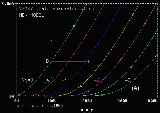
Figure 2. 12AX7 plate curve from the new model.
If you plan to modify or add tube models you'll need to know a bit about the SPICE language. Appendix A has listings of several SPICE files. The first line of a SPICE file contains a title. Data on this line is ignored. The last line consists of the .END statement. Netlist data lines have the general format,
PART node_1 node_2 {additional nodes if applicable} value(s) ; optional commentsComments may appear on lines that start with an asterisk (*) or on data lines following a semicolon (;). Continuation lines begin with a plus sign (+), except for equations, where the portion to the right of the equal sign (enclosed in braces {...}) is restricted to one line. This limitation can present problems with long equations. To get around it, E1 in Equations (4) and (5) has been modeled as a voltage-controlled voltage source that controls IP, which is a voltage-controlled current source. This makes two relatively short equations out of one long one.
I strongly recommend the excellent textbook by Paul W. Tuinenga,10 "SPICE, A Guide to Circuit Simulation & Analysis using PSpice." It contains detailed descriptions SPICE commands and models, including how to perform frequency-domain analysis (.AC), time-domain analysis (.TRAN) and Fourier analysis (.FOUR), which produces a detailed harmonic distortion analysis. In the PSpice Schematics program these instructions are generated by clicking on Analysis, Setup..., then working with the appropriate boxes.
To perform a SPICE simulation with the MicroSim evaluation package, run the Schematics program, then click on File, Open... to open a Schematics data file using the usual Windows navigation techniques. (You can also create a new schematic.) We'll call it filename.SCH in this example. You may edit and save it if you wish. To perform the PSpice simulation, click on Analysis, Simulate. This creates two SPICE language files: filename.CIR containing simulation instructions and filename.NET containing the netlist. These files are then read into the PSpice simulator, which writes text results (voltages, currents, etc.) to filename.OUT and graphics data to filename.DAT for display with Probe, which is run automatically if you have the .PROBE statement in the data file. Probe displays time and/or frequency-domain plots of voltages at selected nodes or currents through selected components. The format of the display is quite versatile. If V(n) is the voltage at node n, VDB(n) is the voltage in dB and VP(n) is the phase. Current display is similarly flexible.
To use the Schematics program I had to create symbols for tubes: a difficult task you can avoid by downloading the models and following the instructions in Appendix B for loading the symbol and SPICE model libraries into PSpice.
| TUBE | MU | EX | KG1 | KG2 | KP | KVB | CCG | CPG | CCP | RGI |
| 6DJ8 | 28 | 1.3 | 330 | 320 | 300 | 2.3P | 2.1P | 0.7P | 2k | |
| 6L6CG | 8.7 | 1.35 | 1460 | 4500 | 48 | 12 | 14P | 0.85P | 12P | 1k |
| 12AX7 | 100 | 1.4 | 1060 | 600 | 300 | 2.3P | 2.4P | 0.9P | 2k | |
| 12AU7 | 21.5 | 1.3 | 1180 | 84 | 300 | 2.3P | 2.2P | 1.0P | 2k | |
| 6550 | 7.9 | 1.35 | 890 | 4800 | 60 | 24 | 14P | 0.85P | 12P | 1k |
| KT88 | 8.8 | 1.35 | 730 | 4200 | 32 | 16 | 14P | 0.85P | 12P | 1k |
The trial and error procedure for finding
tube parmaters is tedious. My
Matlab program for determing them is now available on Finding
SPICE tube model parameters. Two other people have reletant
work.
|
The parameters in Table 1 can be found by a methodical trial and error procedure. To use this procedure, the programs in Appendix A1 through A3 must be employed. Listings A1 and A2 produce plate characteristic curves for triodes and pentodes, respectively. Listing A3 is a portion of the tube library referenced by the .LIB statement in listings A1 and A2. Tubes are modeled as subcircuits, starting with .SUBCKT and ending with .ENDS. .SUBCKT is followed by the model name and then the element node names. We have chosen the order the element nodes to be plate, control grid, cathode, and (in pentodes) screen grid.
To find the parameter values for a new tube, it is best to start with values for a similar existing tube, except for amplification factor MU (µ), which is generally close to the manufacturer's specification. MU is (minus) the change of plate voltage for a given change of grid voltage at constant plate current. This is illustrated by line segment BC in Figure 2, which is a good choice for determining MU because it is located in a region of tube operation far from region (A), where effective MU is reduced. In this case, plate voltage increases by 100V when grid voltage is decreased by 1V while plate current remains constant at 1.9 mA, resulting in MU = 100.
To determine EX and KG1 (X and kG1), run the appropriate plate curve program (Appendix A1 or A2), and observe plate current I(VP) using Probe. Adjust EX and KG1 so that curves for relatively low negative grid voltages (e.g., Vg = 0 or -0.5 for the 12AX7 in Figure 2) match experimental data. Typical values of EX range from 1.3 to 1.4. Line curvature increases with EX. The textbook value of 3/2 for EX is appropriate for equations (1) and (2), where it gives a reasonable average representation of tube operation, but is not really accurate in all regions. KG1 is inversely proportional to plate current for given grid and plate voltages. It usually requires several runs to get a really good match for EX and KG1. MU may need to be adjusted slightly in the process.
For pentodes, the best estimates of MU, EX, and KG1 are obtained from triode-mode curves, i.e., curves taken with the screen grid connected to the plate. Such curves were available for the pentodes listed in Table 1. It is very gratifying to see how parameters obtained from the triode curves (Figure 4) result in excellent fits to pentode and ultra-linear curves (Figures 3 and 5). In running the pentode plate curve program (Appendix A2), operating mode can be set by adjusting parameter TRIMODE (0 for pentode, 40 for ultra-linear (UL), and 100 for triode). VG2NOM (quiescent screen voltage) must also be set appropriately.
KG2 is inversely proportional to pentode screen grid current (I(VG2) in Appendix A2) for given control and screen grid voltages. Curves for pentode screen grid current are rarely published, but screen grid current is usually included in tables of typical tube operation. It is adequate to match a point or two from these tables. KG2 does not need to be estimated with great accuracy to obtain good results in SPICE simulations.
KP (kP) dominates the behavior of the new model in region (A), which is characterized by large negative grid voltage, large plate voltage, and low plate current. Plate current is inversely proportional to KP in this region. Determining KP for a given tube is done entirely by trial-and-error. Triode-mode curves must be used to obtain an accurate estimate of KP for pentodes because published pentode curves tend to have insufficient resolution in region (A).
KVB (kVB) relates to the "knee" of the characteristic curves, and is defined differently in the triode and pentode equations. For pentodes, the knee is proportional to KVB, and is most visible in the pentode-mode curves (Figure 3 for the 6550). Equation (5) does not give an accurate estimate of the knee for all levels of grid voltage, EG . Fortunately, this is not a serious limitation because load lines for practical designs pass close to the knee for EG = 0. (Otherwise there would be a serious impedance mismatch.) The location of the knee for EG = 0 was used to determine KVB in Table 1. For triodes, the knee is proportional to the square root of KVB, and is only apparent when the tube is operated with positive grid voltage. Triode curves for positive grid voltage are published infrequently, for example, the 12AU7 in the Sylvania tube manual.
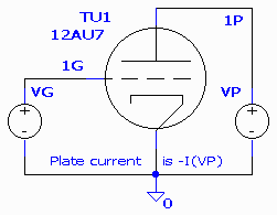 Figure
3. Circuit for obtaining triode characteristic curves.
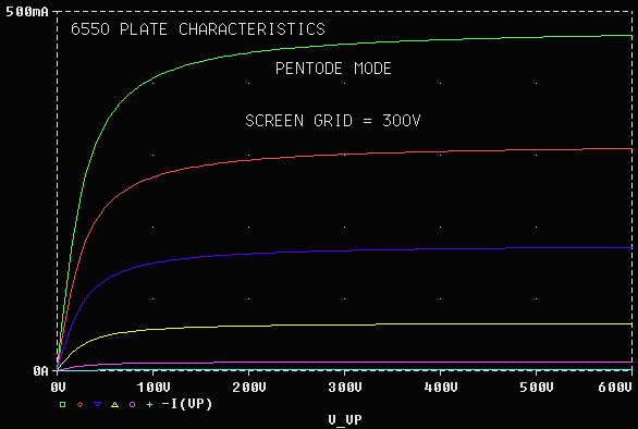
Figure 5. 6550A Pentode mode plate curves.
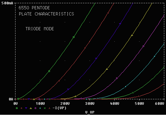
Figure 6. 6550A Pentode, Triode mode plate curves.
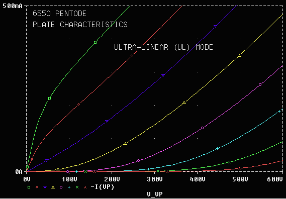
Figure 7. 6550A Pentode, Ultra-Linear (UL) mode plate curves.
Toroidal transformers have much lower leakage flux than traditional
"EI" transformers (so-named after their core geometry). This results in
an extremely large bandwidth. Their only drawback is that their extremely
low magnetic circuit reluctance makes it necessary to balance the dc current
in the two haves of the primary winding extra care. Table 2 gives parameters
for the PAT-4006-CFB output transformer relevant to SPICE simulation. The
PAT-4006-CFB is a semi-custom version of the 100W PAT-4006, available on
special order, designed for four 6550 or similar tubes in push-pull-parallel.
It has a 2 kohm primary winding and two center-tapped secondary windings:
a 5 ohm winding for the speaker and a 20 ohm winding for feedback.
| PARAMETER | SYMBOL | VALUE |
| Total primary inductance | LP | 392.5H |
| Primary leakage inductance | LSP | 0.972mH |
| Quality factor = LP / LSP | Q | 403600 |
| Ultra-linear tap | 40% | |
| Turns ratio | NP/NS | 20 |
| Effective primary capacitance | CIP | 342pF |
| Total primary resistance | RIP | 56 ohms |
| Total secondary resistance | RIS | 0.1 ohms |
Table 2. Parameters of the Plitron PAT-4006-CFB output transformer
To develop the SPICE model (Appendix A3), the center-tapped primary winding with ultra-linear taps is divided into four mutually-coupled segments that have {0.3, 0.2, 0.2, 0.3} of the total number of windings. The inductance of each segment is proportional to the square of the number of windings: {.09LP, .04LP, .04LP, .09LP} = {35.325H, 15.7H, 15.7H, 35.325H}. The ratio of primary to secondary inductance is (NP / NS)2. The transformer's coefficient of mutual coupling, KALL, is entered into the SPICE data file:
KALL = sqrt(1-1/Q) ~= 1-1/(2Q) (The approximation holds for large Q.)
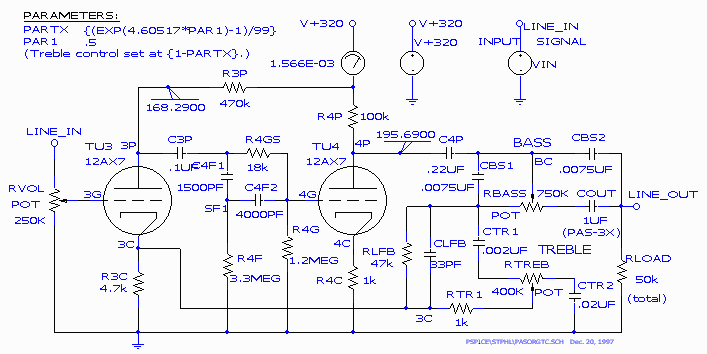
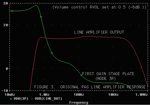
Figure 9. Original PAS-3 line amplifier frequency response at first
gain stage plate (3P)
and output (LINE_OUT). Generated by Probe.
The frequency reponse at the output meets the 20-20,000 Hz ±1dB specification with no problem, but there is a huge 0.5 Hz peak at the first gain stage plate. Altough this peak is well outside the range of hearing it caused definite audible problems, especially on records, where the rotational frequency at 33.3 RPM is-- you guessed it-- almost exactly 0.5 Hz. It was a sort of grindy sound-- perhaps an intermodulation distortion component. A redesign, discussed in Feedback and Fidelity and SPICE and the art of preamplifier design, fixed it beautifully. Listings and excerpts from the output files are in Appendix A4 in part 2.
Output files PASorgTC.cir and PASorgTC.net were generated by schematics. Output file PASorgTC.out was generated by PSpice. Many of the lines in PASorgTC.cir are generated from Schematics by clicking on Analysis, Setup..., then working with the appropriate boxes. .LIB is followed by the name of the library file that contains subcircuits referenced in the program. .PROBE instructs the program to generate data for the PROBE program, which displays graphs of time and/or frequency domain signals at each node. .ac calls for an ac (frequency-domain) analysis, i.e., a frequency sweep with 20 points per decade from 0.01 Hz to 1 MHz. If present, .TRAN calls for a transient (time-domain) analysis, which is required if a Fourier analysis is to be performed.
Appendix A4C shows some of the results of running PSpice, including the dc voltages at each node, the currents drawn by the two voltage sources, and the total power consumption. The first tube is labelled TU3 because TU1 and TU2 were in the phono preamplifier. For example, the plates of TU3 and TU4 are at 168 and 196 volts-- about where they should be (a little over half the supply voltage). A Fourier analysis can be performed for time domain simulations.
Let A be the open-loop (non-feedback) gain of an amplifier. Let B be the fraction of the output voltage that the feedback circuit subtracts from the input. The closed-loop gain (with feedback) of the amplifier is
G = A/(1+AB)
For a feedback loop to be stable, rolloff at both low and high frequencies must be dominated by a single RC network (known to the mathematically literate as a pole on the complex plane) at frequencies where T > 1. Instabilities (near-oscillation situations) appear as peaks or irregularities in the frequency response curve. Such instabilities are shockingly common, even in very expensive high-end amplifiers. In Stereophile equipment reviews, they appear as supersonic peaks of up to 3dB between 50 and 150kHz in frequency response curves measured with 8 ohm resistive loads.6 In a particularly amusing case, an $18,990 amplifier with such a peak received a mixed review, drawing an angry long-winded response explaining how every detail of the setup (down to the power cord) had to be perfect for these incredible amplifiers to sound decent. Ridiculous! (It was a Jadis; I didn't want to mention the brand when I first published this article.)
Response peaks are indicative of poor phase margin- the amount of additional phase shift that can be tolerated before oscillation begins. Since reactive loads tend to increase phase shift, poor phase margin can make an amplifier particularly sensitive to cables and loudspeakers. (Of course, some audiophiles might regard sensitivity to speaker cables as a virtue!) Phase margin should be a standard specification in audio amplifiers: It is one of those seldom-mentioned factors that affect sonic quality. One of the reasons for the current popularity of triode amplifiers without feedback may be that they have no phase margin problem.
Some instability is inevitable when feedback is applied to tube amplifiers with output transformers because the high frequency rolloff of transformers is dominated by a complex pole pair. This necessitates some form of compensation, i.e., an RC network that rolls off response at frequencies lower than the transformer cutoff. The most common technique is to place a capacitor in parallel with the global feedback resistor. Beware of this technique: It works in the near-audio range, but SPICE shows that it can cause response irregularities at extremely high frequencies (as well as inserting RF interference from speaker cables into the amplifier input).
A better approach to compensating feedback loops to add a capacitor between the grid and plate of the tube to which the feedback returns (usually the input tube). The RC network formed by this capacitor and the input grid-stop resistor (a 2k to 10k resistor which should be added if not present) then becomes the dominant frequency-limiting network. The effective capacitance in this RC network is the sum of this capacitor and the tube inter-element capacitance multiplied by the gain of the stage (which is reduced by feedback). This is known as the Miller effect. The proper capacitor value (a few picofarads) must be determined by trial-and-error: The calculations are not simple. This is where SPICE really shines. You can try a new capacitor value and examine its effects in about a minute.
Tube response extends well beyond 1MHz. The .AC sweep in SPICE makes it easy to observe extremes of frequency: I routinely test 0.01Hz to 100MHz. To determine the correct compensation capacitor, observe the signals at the amplifier output and the plate of the input (feedback return) stage at frequencies up to 100MHz. Do this without and with capacitors across the load, which always degrade stability. (Instabilities are visible as high frequency peaks.) Increasing the compensation capacitor rolls off high frequencies but increases stability. If your circuit and output transformer are well-designed, you should be able choose a value for the compensation capacitor that extends your amplifier's frequency response well-beyond the limits of audibility (20kHz) while maintaining stability with the largest shunt capacitance likely to arise from cables and speakers. If you plan to use electrostatic speakers, you will probably need extra compensation capacitance. The final value must be determined experimentally, but it should be close (within 30%) to the SPICE-determined value.
Few of us have signal generators that go down to 0.5Hz, but SPICE shows up a resonance at that frequency in the line stage of the venerable PAS7 (40 dB or more at the input stage plate), which can be quite serious because 0.5 Hz is close to the frequency of record warps. SPICE makes it easy to observe the response at intermediate gain stages as well as the output.
Using SPICE to investigate circuits has been nothing short of a revelation for me. I've been able to try out and rapidly debug new designs that I wouldn't have otherwise risked, and I've answered many nagging questions. I hear a strong correlation between SPICE results (in areas such as stability and RF susceptibility) and subjective sound quality. I fiund SPICE to be far more beneficial than "floobie dust" (extremely expensive premium components alleged to produce magical results).
| This page
created December 8, 2003 |
Images and text copyright (C) 2000-2012 by Norman Koren. Norman Koren lives in Boulder, Colorado. Since 2003 most of his time has been devoted to the development of Imatest. He has been involved with photography since 1964. Designing vacuum tube audio amplifiers was his passion between about 1990 to 1998. |  |